

If you're looking for a new 3D printer for your home or business, consider the benefits of a Delta 3D printer kit. These kits allow you to build your own printer from scratch, providing a hands-on experience and a greater understanding of how your printer works. Not to mention, you'll gain the satisfaction of knowing you built your own printer.
When choosing a Delta 3D printer kit, there are a few factors to consider. First, think about your level of experience with 3D printing and building electronic devices. If you're a beginner, look for kits that come with clear instructions and support documentation. You'll also want to consider the size of the print bed, the quality of the components included, and any additional features like heated beds or automatic bed leveling.
Are you ready to take your 3D printing skills to the next level? Are you looking for a creative new project? Or maybe you're simply interested in learning more about the technology behind 3D printing. Whatever your motivation, a Delta 3D printer kit is an exciting and rewarding option. If you're still unsure where to start, ask yourself what kind of objects you want to print, and what features are most important to you. With some research and a little bit of elbow grease, you'll have a custom 3D printer that meets your exact needs.
10 Best Delta 3D Printer Kit
| # | Product Image | Product Name | Product Notes | Check Price |
|---|---|---|---|---|
|
1
|
 |
The product is ideal for DIY 3D printing projects with a large printing size and fast heating bed.
|
|
|
|
2
|
 |
The product is ideal for upgrading or replacing the hot end assembly on a 3D printer.
|
|
|
|
3
|
 |
The FLSUN SR Super Racer 3D Printer is ideal for fast and accurate 3D printing of various designs and products.
|
|
|
|
4
|
 |
The product is ideal for fast and precise 3D printing of various objects with a large printing size.
|
|
|
|
5
|
 |
The product is ideal for 3D printing in a large format with auto-leveling and filament sensor features.
|
|
|
|
6
|
 |
The product is ideal for quickly printing high-quality 3D objects with a large print size and variety of filaments.
|
|
|
|
7
|
 |
The product is ideal for DIY projects and repairs that require a variety of metric-sized bolts, nuts, washers, and Allen wrenches.
|
|
|
|
8
|
 |
This product is ideal for replacing screws in a variety of laptop and computer brands, including hard disk SATA and SSD M.2.
|
|
|
|
9
|
 |
This product is ideal for fastening nuts onto aluminum profiles.
|
|
|
|
10
|
 |
It is ideal for cooling down the extruder and radiator of a Prusa i3 MK3/2.5 3D printer.
|
|
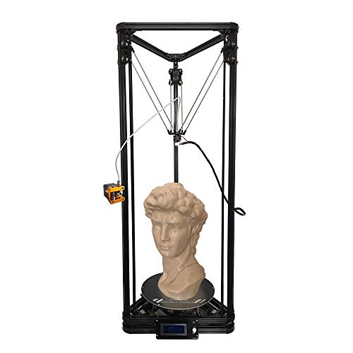
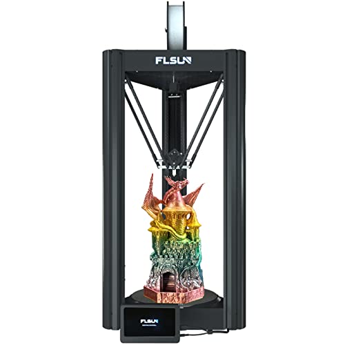
1. Delta 3d Printer: Auto-Level, Large Size, Fast Heat
Get ready to bring your big printing ideas to life with the K280 printer! The printer boasts a pretty large printing size of 280X600mm, ensuring you won't miss the chance to print your favorite big models. With this printer, more printing models will wait for you to explore and create.
The printer comes with a high-quality 24V power supply that provides enough power to ensure good performance. The heating bed can be heated to 110 degrees quickly, allowing you to get started with your printing project in no time.
The K280 printer is versatile and can be used to print almost all printing materials, including ABS, PLA, Wood, Metal, TPU, PNA, Nylon, and more. It's an excellent choice for both beginners and master hands looking to explore the world of 3D printing.
The printer is easy to build and easy to print, making it an ideal choice for anyone looking to get started with 3D printing. Even if you're a beginner, you'll find the K280 printer easy to use and navigate.
The K280 printer also features support for Z-probe auto-leveling, which ensures that your prints come out level and without any issues. This feature makes it easier for you to get started with your printing project and ensures that you get the best possible results every time.
- Large printing size of 280X600mm
- High-quality 24V power supply
- Quick heating bed
- Versatile and can print almost all printing materials
- Easy to build and use
- Supports Z-probe auto-leveling
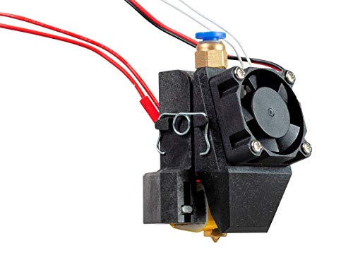
2. Monoprice Delta Mini Hot End Assembly – Full Kit
The Monoprice 3D printer is a high-quality product that offers a rugged design and rigid quality control standards. It is a reliable and affordable option for those looking to purchase a 3D printer. However, it is important to exercise extreme caution when working on any electrical device, including this printer. Always ensure that the power plug is removed and the printer has fully cooled down prior to any maintenance or repair work.
- High-quality product
- Rugged design
- Rigid quality control standards
- Reliable and affordable
- – Requires extreme caution when working on the printer
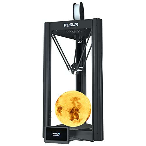
3. Flsun Super Racer Delta 3d Printer
Introducing the Flsun Super Racer (SR) 3D printer, designed to provide an exceptional printing experience with its advanced features. With a printing speed of up to 200mm/s and acceleration of 2800+ mm/s², this printer is 200% faster than the industry standard, allowing you to save time while maintaining the same molding precision quality. The printer is equipped with 3 x 48W high power stepper motors and Three Axis Linkage Technology, providing a smooth and stable printing experience.
The Flsun Super Racer (SR) 3D printer features a large printing volume of Φ10.2" (Diameter) x 13"(H) / 260 x 260 x 330mm, allowing you to print larger objects with ease. The high-precision linear rail guide ensures higher printing accuracy and stability, while reducing noise levels. Additionally, the printer comes with an auto-leveling system, making it easy to start printing. The Flsun Super Racer (SR) 3D printer also features a resume printing function, allowing you to continue printing even after a power outage or lapse occurs. The removable lattice bed is coated with glass, providing good filament viscosity and a replaceable design.
Flsun is committed to providing excellent after-sales service and lifetime technical support to its customers. If you encounter any problems with the Flsun Super Racer (SR) 3D printer, their customer service team is available to respond within 24 hours to assist you.
- High-speed printing of up to 200mm/s and acceleration of 2800+ mm/s²
- Large printing volume of Φ10.2" (Diameter) x 13"(H) / 260 x 260 x 330mm
- High-precision linear rail guide for higher printing accuracy and stability
- Auto-leveling system for easy printing startup
- Resume printing function for power outage or lapse occurrences
- Removable lattice bed with a replaceable design
- Excellent after-sales service and lifetime technical support
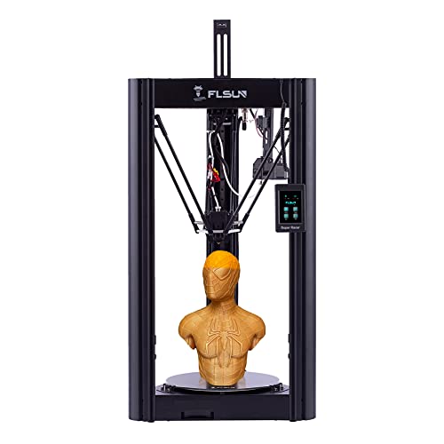
4. Delta Pro 3d Printer: Lightning-Fast With Klipper Firmware
The FLSUN V400 3D Printer is a high-speed printer that can save you more than 70% of printing time. Equipped with 3 x 48W high power stepper motor and pre-installed Klipper Firmware Pad, this printer can print at a normal speed of up to 400mm/s and 8000+ mm/s² acceleration, which is 400% faster than the industry standard. This ensures instant high-speed printing while maintaining the same molding precision quality.
This printer has a large printing volume of Φ11.8" (Diameter) x 16" (H) / Φ300mm (Diameter) X410mm, which is perfect for printing large models. The FLSUN Speeder Pad & High-Speed Integrated Dual-Axis Linear Guide, along with the pre-installed Klipper Firmware 7 Inch FLSUN Speeder Pad, support Wi-Fi remote control and provide higher printing accuracy, stability, and lower noise.
The all-metal direct drive extruder of this printer comes with a pushing force of up to 70N, which is ultra-lightweight, only 135g, and is suitable for printing with flexible consumables and hard consumables such as PLA. The bi-metal 300℃ high-temp nozzle allows you to choose more kinds of filament like PLA PLA+ WOOD TPU ABS PETG PC NYLON(NEED DRIED).
FLSUN V400 upgrade automatic leveling system ensures easy printing with its 25-point smart and precise calibration. The steel spring PEI sheet bed allows for firm bonding and easy model removal. The printer also has a filament detection sensor that automatically pauses printing after the consumables are used and continues printing after replacements. The three-axis linkage technology & all-metal frame structure ensures the stable body of the machine in the process of high-speed printing.
All FLSUN 3D printers are backed by lifetime technical support and 24-hour professional customer service, making it a great choice for those who want a reliable 3D printer that can print large models quickly and efficiently.
- High-speed printing saves more than 70% of printing time
- Large printing volume of Φ11.8" (Diameter) x 16" (H) / Φ300mm (Diameter) X410mm
- All-metal direct drive extruder suitable for printing with flexible and hard consumables
- FLSUN V400 upgrade automatic leveling system ensures easy printing with its 25-point smart and precise calibration
- Steel spring PEI sheet bed allows for firm bonding and easy model removal
- Filament detection sensor that automatically pauses printing after the consumables are used and continues printing after replacements
- Three-axis linkage technology & all-metal frame structure ensures the stable body of the machine in the process of high-speed printing
- Lifetime technical support and 24-hour professional customer service
5. Flsun Speedy 3d Printer- Filament Sensor, Auto-Leveling
The Flsun Super Racer (SR) 3D printer boasts high-speed printing capabilities of up to 200mm/s and 2800+ mm/s² acceleration, thanks to its three-axis linkage technology and 3 x 48W high-power stepper motors. This is 200% faster than the industry standard, allowing users to save more than half of printing time while maintaining the same precision quality.
The printer also features a high-precision linear rail guide and three-axis linkage technology, which provide higher printing accuracy, stability, and lower noise. Its auto-leveling system and removable lattice bed make it easy to start printing, while the coated lattice glass platform ensures good filament viscosity and a replaceable design.
With a large printing volume of 10.2"(L) x 10.2"(W) x 13"(H) / 260 x 260 x 330mm, users can print larger and more complex models with ease. In addition, the Flsun Super Racer 3D printer has a resume printing function that allows it to continue printing even after a power outage or lapse occurs, making it more convenient and efficient.
Users can also enjoy lifetime technical support and 24-hour customer service, ensuring that any questions or issues can be promptly addressed.
- Fast printing speed with high acceleration
- High-precision linear rail guide and three-axis linkage technology for higher accuracy and stability
- Auto-leveling system and removable lattice bed for easy use
- Large printing volume for bigger models
- – No information provided
6. Delta 3d Printer With High Speed Printing
The FLSUN V400 3D printer boasts a fast printing speed at 400mm/s and 8000mm/s ² acceleration, which is 400% faster than the industry standard, thereby saving 70% of printing time. Moreover, its larger printing size of 10.2 inches (L) x 10.2 inches (W) x 13 inches (H)/260 x 260 x 330 mm allows for bigger and more intricate models to be printed.
The printer features a detachable PEI spring steel platform, which ensures solid adhesion of the first layer but also makes it easy to remove the model. The hot bed can be heated up to 110℃, making it suitable for printing various materials such as PLA, PETG, WOOD, ABS, PC, TPU. Additionally, it has a direct extruder design that's ultra-light and short-range, with an extrusion force of up to 70N. The bi-metal structure of the throat allows for high-temperature printing of up to 300℃.
The FLSUN V400 3D printer is easy and fun to use, with a 7-inch wide-angle IPS screen and pre-installed full Klipper firmware, including Klipper, Moonraker, Mainsail, KlipperScreen, WebCAM, and more. It's a plug-and-play device, requiring no additional configuration.
Furthermore, the printer has more functions that make it even more convenient for users. It has a self-developed leveling algorithm that easily solves the first layer problem through 25 points compensation of machining errors. It also supports filament detection, which stops printing automatically after the consumable is used up, and resumes after the consumable is replaced.
- Fast printing speed and large printing size for efficient and effective printing.
- Detachable PEI spring steel platform ensures secure adhesion of the first layer but easy removal of the model.
- Direct extruder design with bi-metal throat structure allows for high-temperature printing.
- Easy and fun to use with a pre-installed full Klipper firmware.
- Self-developed leveling algorithm and filament detection add to the printer's convenience.
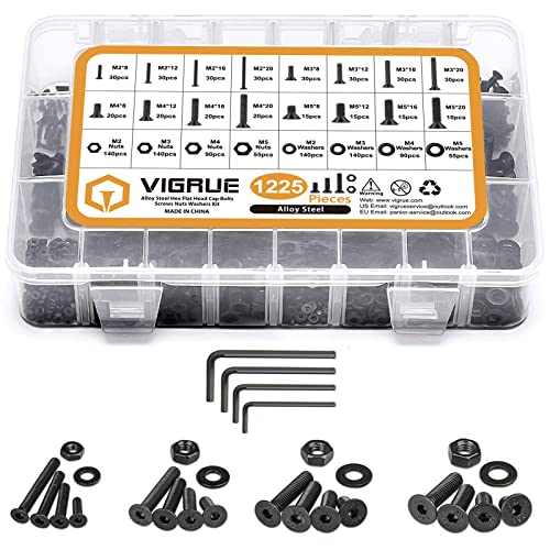
7. Vigrue Socket Cap Screws Kit: 1225pcs Assortment
The Screw Assortment Kit is a must-have for anyone who needs to work with screws. This kit includes M2, M3, M4, and M5 screws in various lengths of 8mm, 12mm, 16mm, and 20mm. The kit comes with matching nuts and washers, making it easy to find the right parts for your project. With a total of 1225 pieces, you'll have everything you need to get the job done.
The kit comes in a handy box that is organized by size, making it easy to find the bolts you need. The box is durable and sturdy, ensuring that your tiny parts are safe and secure. The hex flat head bolts, washers, and nuts assortment kit serves a wide range of uses, making it perfect for professionals, amateurs, repairmen, and DIY enthusiasts. The kit covers the most common sizes, making it a versatile addition to any toolbox.
The screws in this kit are made of high-quality 10.9 Grade Alloy Steel, which features superior corrosion resistance. This ensures that your screws will last a long time, even in harsh conditions. The reliable quality of this kit makes it an excellent investment for anyone who needs to work with screws.
- Includes a wide range of screw sizes and lengths
- Comes with matching nuts and washers
- Organized by size in a durable and sturdy case
- Serves a wide range of uses for professionals, amateurs, repairmen, and DIY enthusiasts
- Made of high-quality 10.9 Grade Alloy Steel with superior corrosion resistance
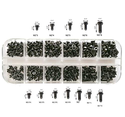
8. Tiny Tech Screw Set For Laptops
The Persberg 360PCS Personal Computer Screws Standoffs Set Kit is a must have for anyone looking for a comprehensive set of screws and standoffs for their personal computer. The kit comes with a total of 360 pieces, making it easy to find and use whenever needed. It is perfect for SSD M.2, PC case, power supply, motherboard, hard drives, fan and floppy/CD-ROM/DVD-ROM drives fixed installation.
The kit is compatible with all universal laptop and notebook computers, making it a versatile option for those who have multiple devices. It includes 12 of the most commonly used sizes, including M2*3, M2*4, M2*5, M2*6, M2*8, 2X10, M2.5*4, M2.5*5, M2.5*6, M2.5*8, M3*5, and M3*8. This ensures that users have the right size for their specific needs.
The screws and standoffs are made of high-quality alloy steel, which is known for its durability and strength. They are also oxidative blackened, providing an added layer of protection against rust and corrosion. The kit comes with a clear box for easy storage and organization, making it easy to find the right screw or standoff whenever needed.
- Comes with 360 pieces for a comprehensive set
- Compatible with all universal laptop and notebook computers
- Includes 12 of the most commonly used sizes
- Made of high-quality alloy steel for durability and strength
- Oxidative blackening provides added protection against rust and corrosion
- Comes with a clear box for easy storage and organization
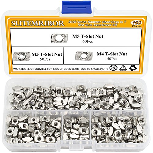
9. Aluminum Profile Hammer-Head Nuts – 160-Pc Set.
This Hammer Head Drop-in T-Slot Nuts Assortment Kit is made of high-quality carbon steel, ensuring high hardness and a long service life. The nuts are Nickel-plated, providing good rust resistance and better performance. This kit includes a total of 160 pieces of nuts, comprising of 2020 series M3 x 50 pieces, M4 x 50 pieces, and M5 x 60 pieces, which are all stored in a transparent plastic box, making it convenient for storage and use. The nuts have a feature where they can be directly inserted into the aluminum slot hole in any assembly post, and the back spring ball can be fixed in its position, making the installation process simple and reliable. These T-Nuts are suitable for 2020 series aluminum profiles and are widely used for building industrial aluminum frame structures, 3D printers, CNC Routers, CNC laser cutters, and robotics projects.
The Hammer Head Drop-in T-Slot Nuts Assortment Kit's solid construction guarantees a long lifespan and exceptional durability. The Nickel-plating on the surface provides excellent rust resistance and better performance. The package comes with a transparent plastic box, making it easy to store and use the nuts. Moreover, the nuts' feature of being able to be directly inserted into the aluminum slot hole makes the installation process simple and reliable. Lastly, the kit's versatility allows for a wide range of applications, including building industrial aluminum frame structures or robotics projects.
Constructed from high-quality carbon steel, the Hammer Head Drop-in T-Slot Nuts Assortment Kit is highly durable and long-lasting. The Nickel-plating on the surface provides excellent rust resistance and better performance. The nuts are packaged in a transparent plastic box, making it easy to store and use them. The nuts' unique feature allows them to be directly inserted into the aluminum slot hole, making the installation process simple and reliable. Lastly, the kit's versatility allows for a wide range of applications, including building industrial aluminum frame structures or robotics projects.
- High-quality carbon steel construction
- Long service life
- Nickel-plated surface for rust resistance and better performance
- Simple and reliable installation process
- Suitable for a wide range of applications
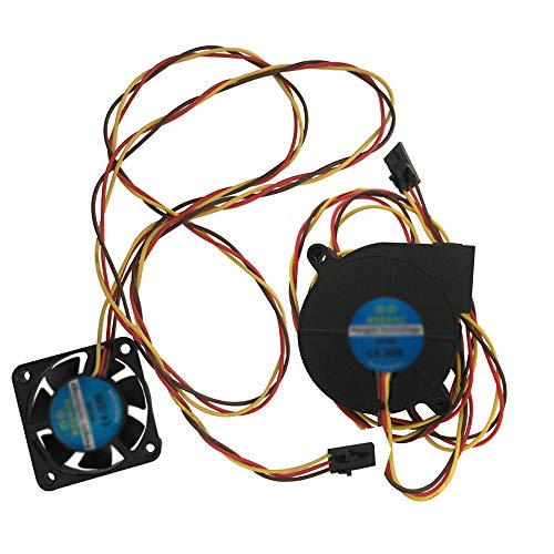
10. Prusa 3d Printer Dual Blower Fan Kit
This Dual Ball bearing fan is designed to provide efficient cooling to the hotend of Prusa i3 MK3 MK3S MK2/2.5 3D printers. It has a long lifetime of 50000 hours, which has been tested under 40-degree temperature. The fan operates on 5V DC 0.1A power, and has a power connector of 3 pins with RPM measuring function.
It is important to note that the fan has two sides, but the side with the sticker must always face the hotend. This is not visible when the fan is mounted, but if the sticker side is not facing the hotend, the cooling won't work properly. The package includes one 5015 Front hotend blower fan and one 4010 Left hotend fan.
- Long lifetime of 50000 hours tested under high temperature
- Efficient cooling of the hotend
- RPM measuring function for better control
- Package includes two fans for complete coverage
- – Mistaking the side of the fan with the sticker could lead to improper cooling
Best Delta 3D Printer Kit FAQs
Can the Delta 3D Printer Kit be upgraded or modified?
Yes, the Delta 3D Printer Kit can be upgraded or modified. In fact, one of the advantages of a kit is that it allows for customization and flexibility. There are many resources available online that provide guidance on how to upgrade or modify a Delta 3D Printer Kit. Some popular modifications include adding new extruders, upgrading the hot end, and replacing the bed with a larger one. Additionally, many 3D printing enthusiasts enjoy experimenting with new materials and techniques, which often require modifications to their printer. It is important to note that any modifications or upgrades should be done with caution and with a thorough understanding of the technology. It is also important to ensure that any modifications do not void the warranty of the printer. Overall, the Delta 3D Printer Kit is a great option for those who want to experiment with 3D printing and have the ability to modify and upgrade their printer.
How difficult is it to assemble a Delta 3D Printer Kit?
Assembling a Delta 3D printer kit can be a challenging task, especially for beginners who have little to no experience with 3D printers. The process can take anywhere from a few hours to several days, depending on the complexity of the kit and the user's level of expertise.
The first step is to carefully read the instructions provided with the kit and familiarize yourself with the different components and their functions. It is important to have a systematic approach and follow the instructions step by step to ensure that the printer is assembled correctly.
One of the key challenges in assembling a Delta 3D printer kit is calibrating the printer. This involves adjusting the height of the printer's arms and the position of the print bed to ensure that the printer can accurately print objects.
Overall, assembling a Delta 3D printer kit requires time, patience, and attention to detail. However, with the right approach and a willingness to learn, anyone can successfully assemble a Delta 3D printer kit and enjoy the benefits of 3D printing.
What is included in the Delta 3D Printer Kit?
The Delta 3D Printer Kit is a complete package that includes all the necessary components required to build a functional Delta 3D Printer. The kit includes a set of aluminum extrusion frames for building the printer's structure, a hotend for extruding the filament, and a heated bed for printing on. It also includes a control board, LCD screen, and all the wiring necessary for powering the printer and controlling its movements. Additionally, the kit comes with a set of stepper motors, belts, and pulleys, as well as a set of endstop switches for accurate positioning. The kit is designed for easy assembly, and it includes comprehensive assembly instructions to guide users through the process. Overall, the Delta 3D Printer Kit is an excellent choice for anyone looking to build their own Delta 3D printer from start to finish.
What is the maximum build volume of the Delta 3D Printer Kit?
The maximum build volume of the Delta 3D Printer Kit depends on the specific model and manufacturer. However, in general, Delta 3D printers are known for their large build volumes compared to other types of 3D printers. The build volume is the maximum size of the object that can be printed by the printer, and it is determined by the dimensions of the printer's build platform. Some Delta 3D printers can have build volumes of up to 300mm in diameter and 500mm in height, allowing for the creation of larger objects or multiple objects in a single print job. It is important to research the specific model and brand of the Delta 3D printer kit to determine its maximum build volume and other important features before making a purchase.
What types of materials can be printed with a Delta 3D Printer Kit?
A Delta 3D Printer Kit is a versatile printer that can print a wide range of materials. It's capable of printing with a variety of materials, including PLA, ABS, PETG, Nylon, TPU, and more. These materials are widely used in the 3D printing industry for their durability, flexibility, and ease of printing.
PLA (Polylactic Acid) is the most common material used in 3D printing due to its ease of printing and low cost. ABS (Acrylonitrile Butadiene Styrene), on the other hand, is known for its durability and flexibility. PETG (Polyethylene Terephthalate Glycol) is a popular material known for its toughness and resistance to impact.
Nylon is another popular material that is known for its strength and flexibility. TPU (Thermoplastic Polyurethane) is a flexible material that is ideal for printing items such as phone cases, watch bands, and other wearable items.
In summary, a Delta 3D Printer Kit can print a wide range of materials, including PLA, ABS, PETG, Nylon, TPU, and more. The choice of material depends on the specific application and the desired properties of the final product.